The info below describes the process of developing one of the PCBs I designed during the summer of 2014.
Initial layout
I begin my design on a breadboard using the through-hole version of the ATMega 328 chip - the same microcontroller used on the Arduino Uno development board. My project needed to consume as little power as possible, so a 3.3v switching regulator was used. While the UNO runs at 5v, the 328 chip can also run at 3.3v. Per the data sheet, I replaced the 16mhz clock used on the UNO with an 8mhz oscillator.
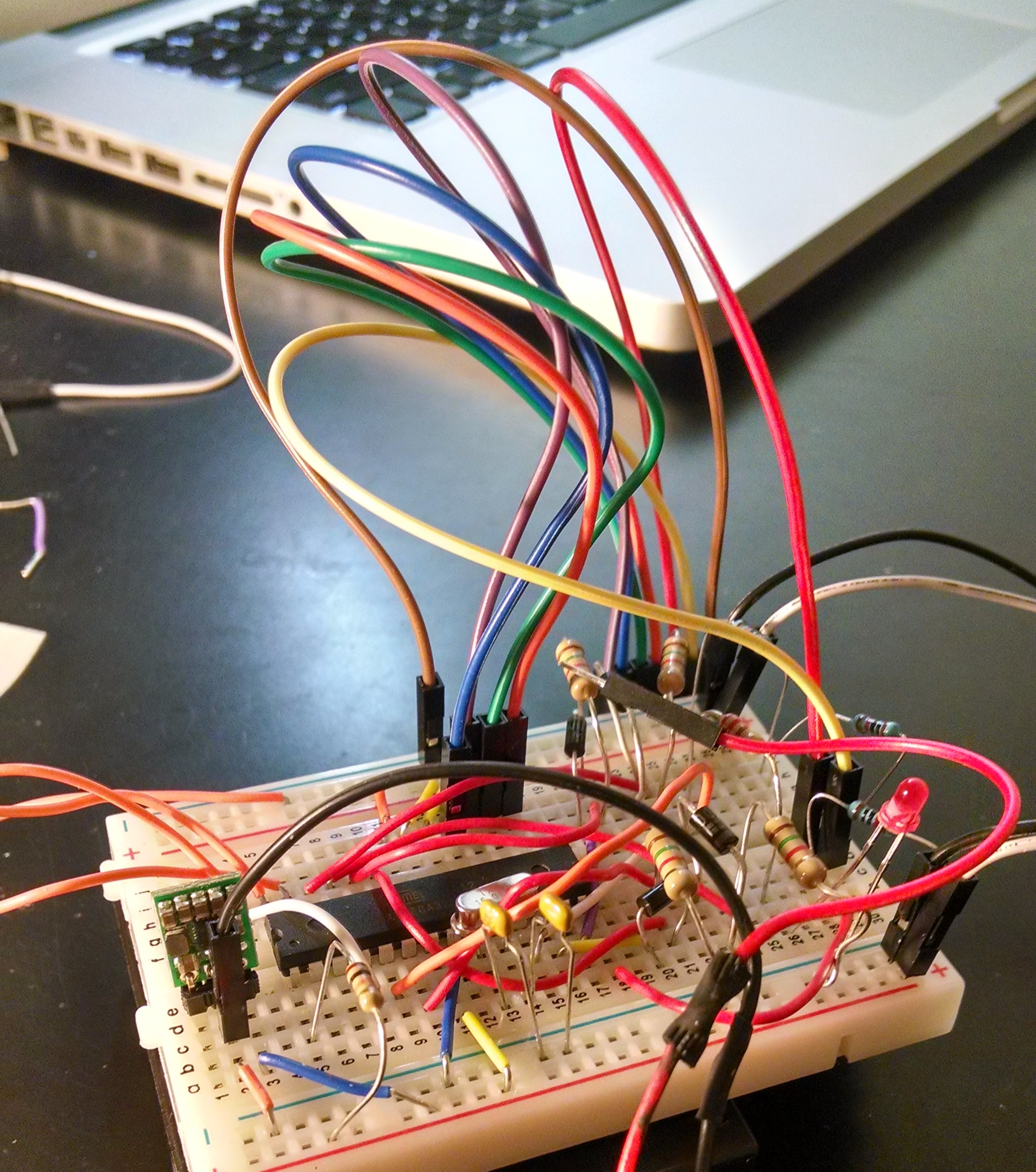
Once I was satisfied with the performance of the design on a breadboard, I moved to Fritzing to create the first version of the PCB.
First PCB in Fritzing
Fritzing is an open-source PCB design software package meant to ease the process of PCB design. One of Fritzing’s most commonly cited features is the “breadboard layout.” This allows a user to visualize the board layout on a virtual breadboard.
My only complaint with Fritzing is that it was a bit buggy on the Mac, often making zooming and other routine tasks a struggle. Overall, however, Fritzing seems to be a competent place to start when designing PCBs.
Improving the design in Eagle
I decided to improve the design in Eagle, an extremely popular software package among hobbyists and ‘makers.’ Although KiCad is a comparable and equally popular open-source alternative, the available component libraries for Eagle were enough to convince me to learn it instead of KiCad.
Schematic view
Like many PCB design programs, any board design in Eagle begins in schematic view. Fortunately, all of the components for my board were already available in various Eagle libraries, so I was able to immediately drag these into the schematic view and begin building out the schematic for my board.
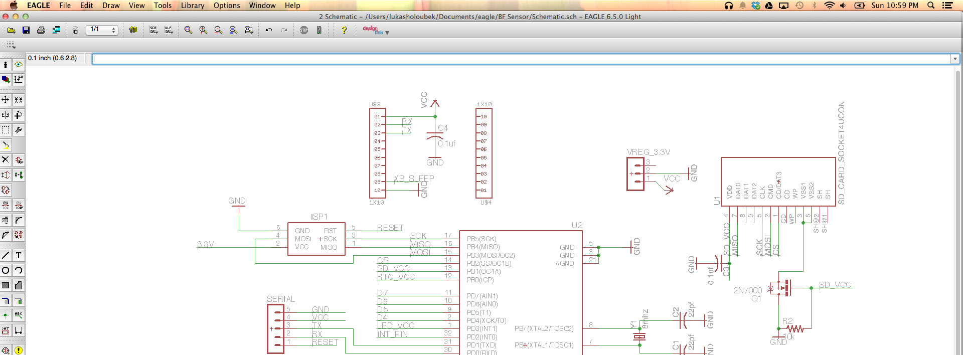
The most common complaint about Eagle, and one that I share, is that the interface is a bit counter intuitive at first. Functions as simple as copy and paste do not follow typical UX conventions, and Eagle therefore takes a while to get accustomed to. Despite the UI quirks, Eagle is an immensely capable piece of software.
PCB view
After completing the schematic, I then opened up PCB view to begin routing the traces on the PCB. Eagle has an autorouter that is quite capable, but decided to route traces by hand.
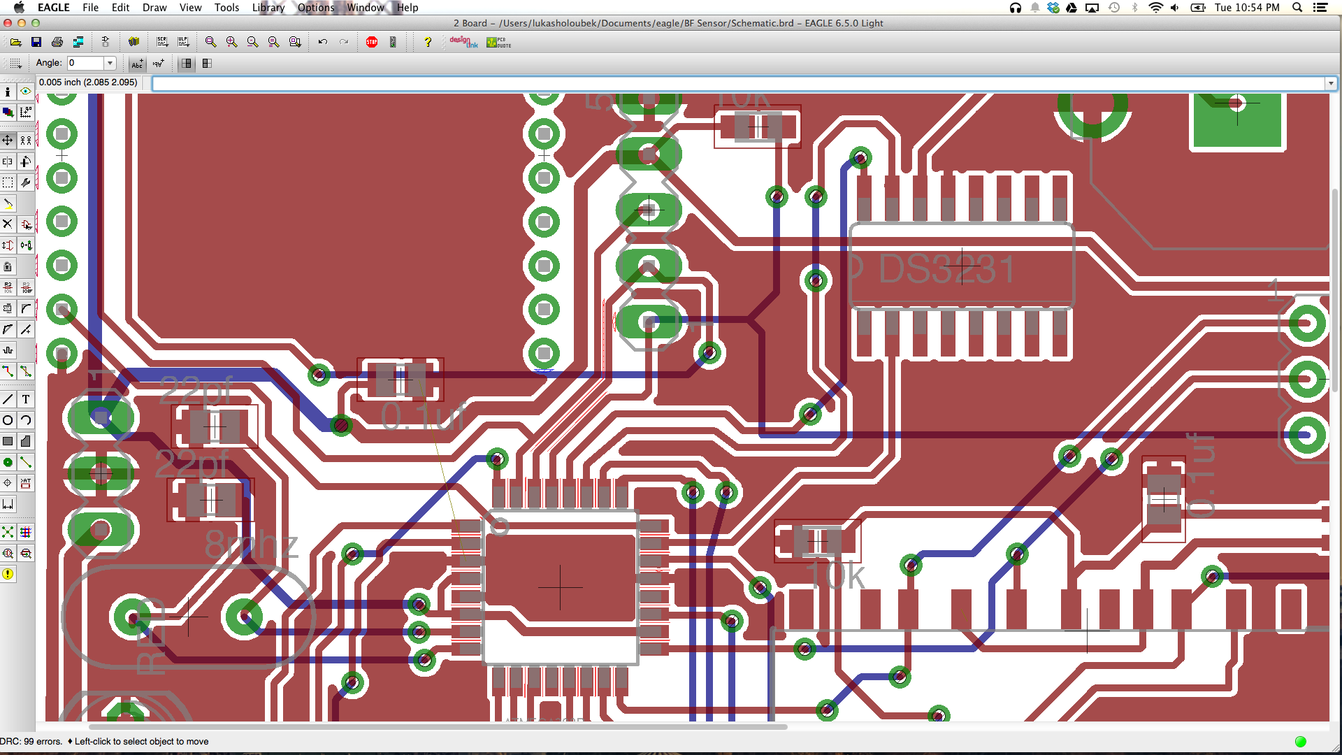
When I finished arranging components and routing my traces, I checked my tolerances using Eagle’s design rule check. The key here is to enter specifications from the print house to make sure that a design isn’t sent off if the print house is unable to fabricate it to those tolerances. Design rules for OSH Park, a popular PCB printer, can be found here.
Getting the board printed
Once the board was designed, I explored a view different options for printing. I’ve had good luck with OSH Park in the past - boards are reasonably cheap and of exceptional quality. However, the turn time for boards is a minimum of two weeks. While this is reasonable, I wanted to accelerated this project.
Prototypes from Advanced Circuits
Advanced Circuits in Denver, CO, provides a service they refer to as “barebones boards.”. These boards are relatively inexpensive and have a 3 day(!) turn time. The catch? Silk screens aren’t included, making assembly a bit tough.
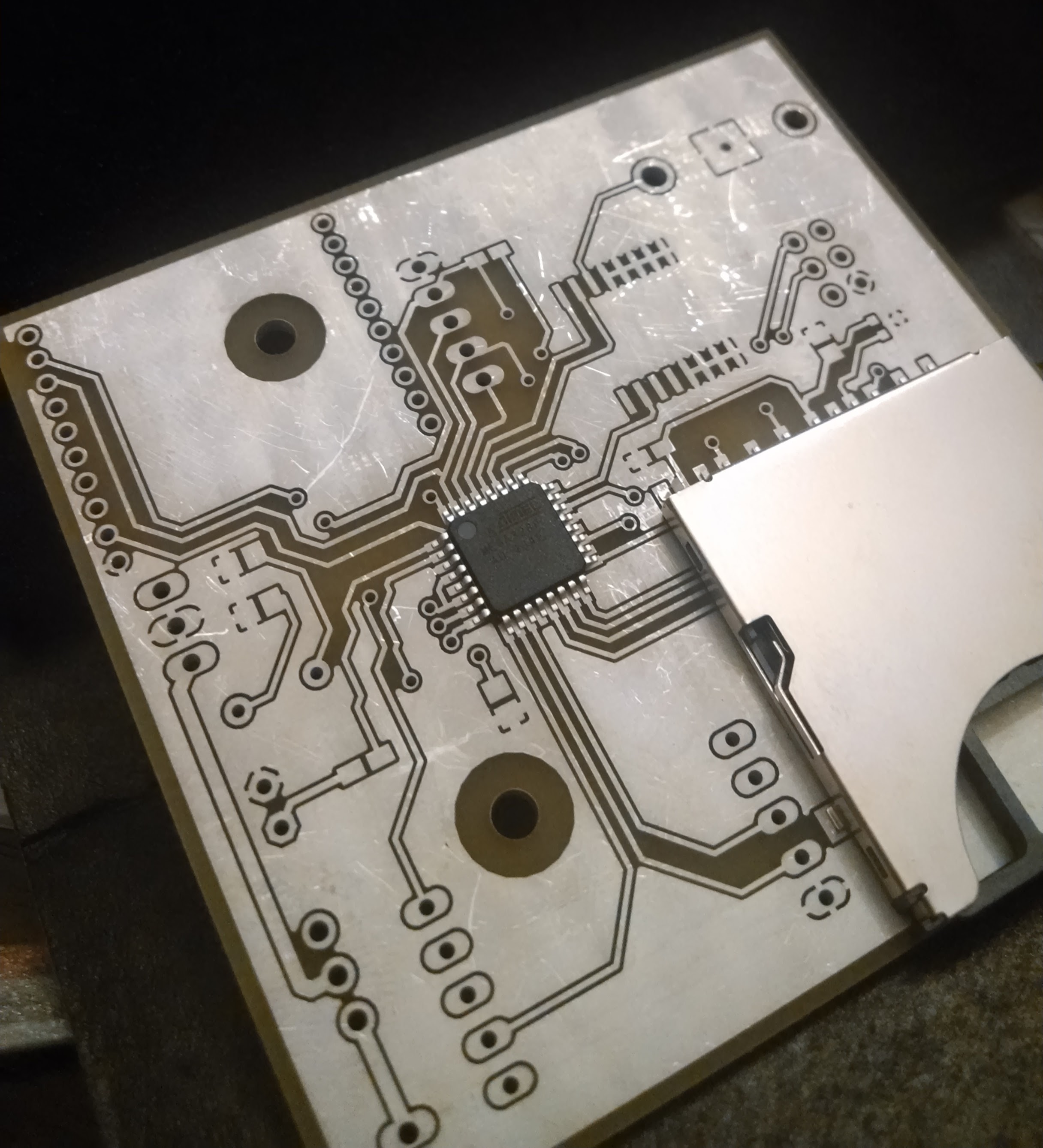
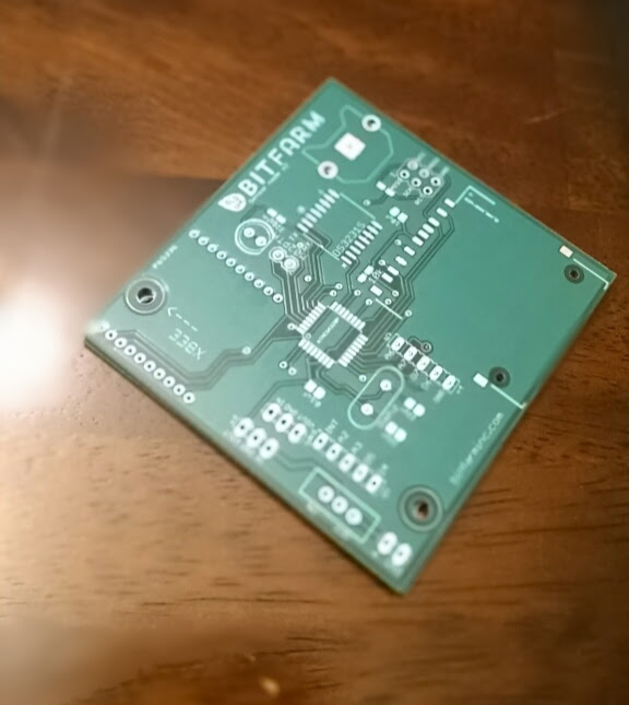
Final boards
I also had the final boards printed through Advanced Circuits after slightly modifying the design. The final boards turned out great, and I’m extremely happy with the consistent quality. The turnaround time was just over two weeks, and the prices were reasonable for the quantity purchased. OSH Park is definitey the way to go for smaller board runs, but Advanced Circuits becomes competitive when more than 10 boards are being printed. The final boards are below: